ESP32 connect OLED display ( SSD1306 )

ESP32 connect OLED Display

We have ESP32 WiFi Module and We'd like to connect to some small display.Easy way to interface with small display is OLED on I2C Bus. because of use 4 wire to connect.
We choose to OLED is  0.96 inch 128x 64 OLED  and SSD1306 Library from Adafruit.
and we test on Nano32 development board from Gravitech and Maker Asia.


Wiring Diagram


OLED SSD1306 Pin SCL  to  ESP32 GPIO 22
OLED SSD1306 Pin SDA  to  ESP32 GPIO 21

IDE and  Library

We use Arduino IDE to develop code in C/C++.
If you are new for this see How to develop ESP32 on Arduino IDE first.
We use Arduino IDE 1.8.5
Add SSD1306 Library
Goto Menu Sketch => Include Library => Manage Libraries


Then search "ssd1306" and Install Adafriut SSD1306 by Adafriut Version 1.x.x


Edit Some Library code for OLED 128x64 only.
When install library done.
In folder Documents / Arduino / libraries /
We will found Adafriut_SSD1308.ccp and Adafriut_SSD1306.h


Edit Adafruit_SSD1306.ccp line 206
Wire.begin();   to  Wire.begin( 21, 22 );


Edit Adafruit_SSD1306.h line 55
0x3D    to   0x3C


and line 73
uncomment this line for use  #define SSD1306_128_64


Example Code

Goto Menu  File => Examples => Adafruit SSD1306 => ssd1306_128x64_i2c
and edit code line 61 in Setup Function.
change address i2c from 0x3D  to  0x3C.


Then upload code to your ESP32 development board.


Test with ESP32 Thing form Sparkfun


Reference

http://esp32.net/


My Website

email : info@softpowergroup.net  ,amphancm@gmail.com  Tel .+6681-6452400

Android and Arduino IoT


LINE : adunfong
FaceBook : https://www.facebook.com/adun.nantakaew
email: amphancm@gmail.com


ESP8266 Weather Station with Color TFTLCD


ESP8266 Weather Station with TFTLCD

In this project, we'll learn how to make a weather station using an ESP8266 WiFi Module and a 2.2" TFT LCD display. ( 240 x 320 65K)
This project pulls weather data using the Wunderground API. It displays the date, time, current weather conditionals, 4-day forecast and even moon phases.

Hardware

  1. ESP8266 WiFi Module ( ESP8266 DevKit or NodeMCU )
  2. TFT LCD 2.2 Inch  : TFT01-2.2SP from Electrofreak (SPI Bus )


Wiring Diagram

TFT LCD Pin VCC
TFT LCD Pin GND
TFT LCD Pin CS  to GPIO_5
TFT LCD Pin RST to RST
TFT LCD Pin DC to GPIO_2
TFT LCD Pin MOSI to GPIO_13
TFT LCD Pin CLK to GPIO_14
TFT LCD Pin LED to +3.3 V.
TFT LCD Pin MISO ( not use )

You can test TFTLCD first.see detail.
http://microcontrollerkits.blogspot.com/2015/11/esp8266-wifi-tftlcd.html


Source code

Original Code form squix78
https://github.com/squix78/esp8266-weather-station


Arduino Library
Weather Station Library
Adafruit ILI9341 Library
Adafruit GFX Library
WifiManager Library

Reference
https://learn.adafruit.com/wifi-weather-station-with-tft-display/overview
https://www.wunderground.com/weather/api


My Blog


My Website
email : info@softpowergroup.net   amphancm@gmail.com Tel . +6681-6452400

Facebook https://www.facebook.com/softpowergroup/


ESP8266 Sent Sensor Data to Firebase Realtime Database


ESP8266 Sent Sensor Data to Firebase Realtime Database

What is Firebase ?
Firebase is a platform that helps you quickly develop high-quality apps ( Mobile and Web Apps),
grow your user base, and earn more money.

Firebase is made up of complementary features that you can mix-and-match to fit your needs.
Show in May 2016, at the Google I/O conference

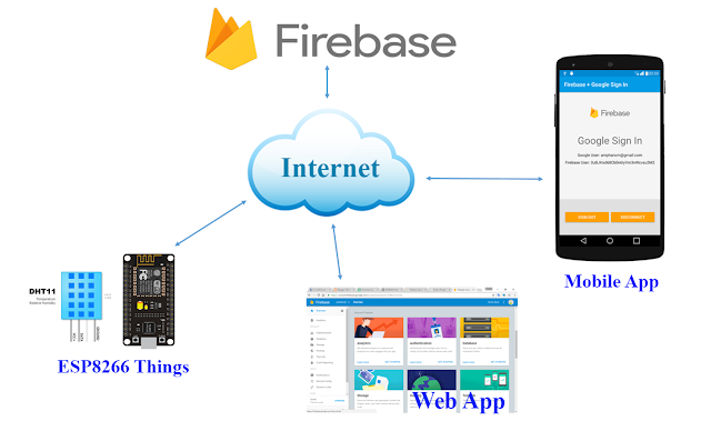
System Diagram

Hardware
1.ESP8266 WiFi Module or NodeMCU ( We use ESP8266 12E )
2.Temperature and Humidity Sensor DHTxx ( we use DHT22 or AM2302 )
3.OLED Display for Option

Wiring Diagram


My ESP8266 WiFi Model Development Board


Software

ESP8266 Source code on Github ( Arduino IDE )
https://github.com/amphancm/ESP8266-Firebase


Arduino Library
Firebase Arduino Library
WiFi Connector
DHT Sensor
Adafriut GFX ( OLED Display )


Reference
        • Firebase Arduino [GitHub]
        • Firebase Arduino - Documentation
In Thai
มาลองใช้งาน Firebase Realtime Database กับ ESP8266 ด้วย Arduino กันเถอะ
http://www.akexorcist.com/2016/11/firebase-and-esp8266-with-arduino.html

ESP8266 ESP8285 กับการใช้งาน Firebase ระบบฐานข้อมูลเรียลไทม์จาก Google


Demo with Android App


My Website
email : info@softpowergroup.net   Tel .081-6452400

ESP32 develop with Arduino IDE


ESP32 Develop with Arduino IDE
I've just ESP32 Development Board call Nano32 from Gravitech / MakerAsia.
The new ESP32 WiFi chip from ESPressis System improve over ESP8266 WiFi Module.
see the spec.
http://microcontrollerkits.blogspot.com/2016/10/esp32-development-board-form-gavitech.html

Now ( Oct10 ,2016 ) announced Arduino Core for ESP32 WiFi Chip

https://github.com/espressif/arduino-esp32

The following was the setup environment for ESP32 with Arduino IDE


STEP 1  
Download Arduino core for ESP32.


Then Unzip and we will copy all this file to Arduino IDE directory or path later.


STEP 2
If Install Arduino IDE already. Find the path of Arduino IDE Installation directory.

Example
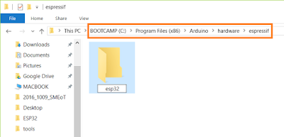
My Computer in C:/Program Files (x86)/Arduino


Make New folder name espressif in the hardware directory


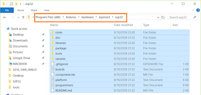
and make subfolder in espressif  folder name esp32


Then copy all files from download into this directory. ( esp32 )


or Use Command Line 
cd hardware
mkdir espressif
cd espressif
git clone https://github.com/espressif/arduino-esp32.git esp32


STEP 3
Use Python 2.7 Command 
if you don't have it. download Python 2.7 https://www.python.org/downloads/


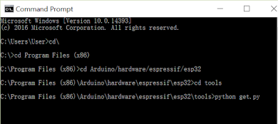
Then Use Command Line
cd esp32/tools
python get.py

My Example


STEP 4 Open Arduino IDE
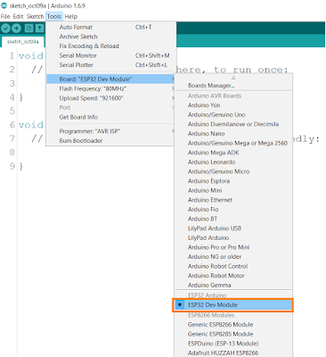
Now, You will have Board ESP32 Dev Module and Select port


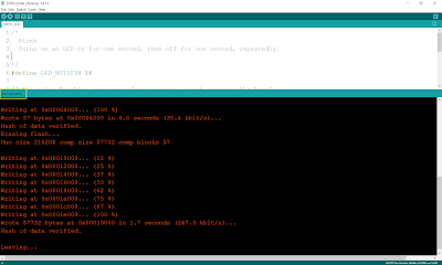
STEP 5 Test Compile and Upload Example Code

Test Blink in Example Code


Done Uploading.
Upload code faster than ESP8266 very much.

Reference ( Fixed some bugs ) Thank you for that.
http://www.ayarafun.com/2016/10/arduino-esp32-first-touch/

Nano32 Board
https://www.gravitechthai.com/product_detail.php?d=1470


My Website
email : info@softpowergroup.net   Tel .081-6452400 ( Thailand )


ESP32 Development Board form Gravitech and MakerAsia


ESP32 Development Board ( Nano32 )

Nano32 is new ESP32 development board. It’s made by South East Asia based Gravitech, and combines ESP32 with an FTDI chip for USB to serial programming through the micro USB port. It also includes two buttons, and breadboard-friendly headers.


NANO32 Features

  • 40MHz Crystal for CPU, 32.768KHz Crystal for RTC and low power operation
  • 4MB Flash (32Mbit)
  • FTDI231 for USB to Serial
  • Auto-Reset for automatic flash
  • 3.3V 0.5A Regulator (tested for working up to 1A)
  • 2.5dBi Peak Gain, 0.5dBi Average Gain Chip Antenna
  • High quality PCB: design and manufacture in Thailand

Key Features    
  • Xtensa® Dual-Core 32-bit LX6 microprocessors, up to 600 DMIPS
  • Integrated 520 KB SRAM
  • Integrated 802.11BGN HT40 Wi-Fi transceiver, baseband, stack and LWIP
  • Integrated dual mode Bluetooth (classic and BLE)
  • 4 MByte flash (32Mbit)
  • 2.2V to 3.6V operating voltage
  • -40°C to +125°C operating temperature

Wi-Fi   
  • 802.11 b/g/n/e/i
  • 802.11 n (2.4 GHz), up to 150 Mbps
  • 802.11 e: QoS for wireless multimedia technology
  • WMM-PS, UAPSD
  • A-MPDU and A-MSDU aggregation
    Block ACK
  • Fragmentation and defragmentation
  • Automatic Beacon monitoring/scanning
  • 802.11 i security features: pre-authentication and TSN
  • Wi-Fi Protected Access (WPA)/WPA2/WPA2-Enterprise/Wi-Fi Protected Setup (WPS)
  • Infrastructure BSS Station mode/SoftAP mode
  • Wi-Fi Direct (P2P), P2P Discovery, P2P Group Owner mode and P2P
  • Power Management
  • UMA compliant and certified
  • Antenna diversity and selection

Bluetooth 
  • Compliant with Bluetooth v4.2 BR/EDR and BLE specification
  • Class-1, class-2 and class-3 transmitter without external power amplifier
  • Enhanced power control
  • +10 dBm transmitting power
  • NZIF receiver with -98 dBm sensitivity
  • Adaptive Frequency Hopping (AFH)
  • Standard HCI based on SDIO/SPI/UART
  • High speed UART HCI, up to 4 Mbps
  • BT 4.2 controller and host stack
  • Service Discover Protocol (SDP)
  • General Access Profile (GAP)
  • Security Manage Protocol (SMP)
  • Bluetooth Low Energy (BLE)
  • ATT/GATT
  • HID
  • All GATT-based profile supported
  • SPP-Like GATT-based profile
  • BLE Beacon
  • A2DP/AVRCP/SPP, HSP/HFP, RFCOMM
  • CVSD and SBC for audio codec
  • Bluetooth Piconet and Scatter-net

Sensors    
  • Ultra low noise analog amplifier
  • Hall sensor
  • 10x capacitive touch interface
  • 32 kHz crystal oscillator

32x GPIO    
  • 3 x UARTs, including hardware flow control
  • 3 x SPI
  • 2 x I2S
  • 12 x ADC input channels
  • 2 x DAC
  • 2 x I2C
  • PWM/timer input/output avalible on every GPIO pin
  • OpenOCD debug interface with 32 kB TRAX buffer
  • SDIO master/slave 50 MHz
  • Supports external SPI flash up to 16 MB
  • SD-card interface support

Security Related
  • IEEE 802.11 standard security features all supported, including WFA, WPA/WPA2 and WAPI
  • Secure boot
  • Flash encryption
  • 1024-bit OTP, up to 768-bit for customers
  • Cryptographic hardware acceleration:
    – AES
    – HASH (SHA-2) library
    – RSA
    – ECC
    – Random Number Generator (RNG)


Development Support


My Website
email : info@softpowergroup.net   Tel .081-6452400

ESP8266 WiFi Module Control RGBLED

ESP8266 WiFi Module Control RGBLED

This project we use ESP8266 WiFi Module to control RGB LED via WiFi Network.

System Diagram


Hardware

1.ESP8266 WiFi Module ( or NodeMCU )
2.RGB LED ( common anode (A) ) if you to use common cathode ( K ) must edit code.
3.OLED Display ( Option )


Wiring Diagram ( RGB LED Common Anode + )


ESP8266 Pin GPIO_14 to LED R
ESP8266 Pin GPIO_12 to LED G
ESP8266 Pin GPIO_13 to LED B

Option OLED Display
 ESP8266 Pin GPIO_05  ( SCL )  to  OLED pin SCL
 ESP8266 Pin GPIO_04  ( SDA )  to  OLED pin SDA


ESP8266 Source Code  ( IDE use Arduino IDE 1.6.8 )

Source Code on GitHub
https://github.com/amphancm/ESP8266WiFi_RGBLED

Original WebServer for NodeMCU Code from
https://github.com/dimsumlabs/nodemcu-httpd


My Website
http://softpowergroup.net/
email : info@softpowergroup.net   Tel .081-6452400
Google+  https://plus.google.com/+SoftpowergroupNetThailand/

Arduino Bluetooth Control LED

Arduino Bluetooth Control LED
Arduino Project which you want to control LED  via Bluetooth.

Hardware

1. Arduino UNO Board or compatible Board
2. Serial Bluetooth Module. ( HC-06 )
3. LED with Resistor 300 - 1K ohm x 8


Wiring Diagram

Output LED 1 to Pin 2 ( Arduino Board )
Output LED 2 to Pin 3
Output LED 3 to Pin 4
Output LED 4 to Pin 5
Output LED 5 to Pin 6
Output LED 6 to Pin 7
Output LED 7 to Pin 8
Output LED 8 to Pin 9

Bluetooth Module Tx to  Pin 0
Bluetooth Module Rx to  Pin 1


Control with Android

Android App on Google Play  


My Website
email : info@softpowergroup.net   Tel .081-6452400

Facebook https://www.facebook.com/softpowergroup/